Configuring the Network Explorer
Celonis Academy course available
See the Celonis Academy - Set up the Network Explorer course for help guiding you through the Network Explorer setup.
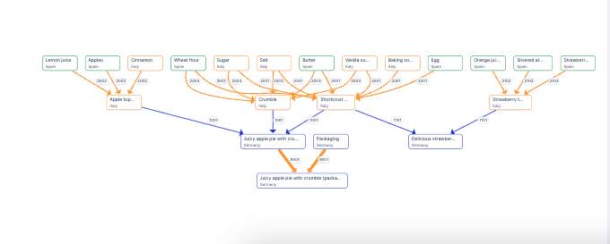
The Network Explorer component allows you to examine how objects are related across your business. By choosing different node dimensions, you can explore your object-to-object relationships by country, plant, material, or distribution and the KPI to display for each object.
Network Explorer provides the visualization for the end-to-end lead time app for object-centric process mining, and supports advanced use cases such as material margins or carbon footprint calculations.
 |
Network visualizations rely on both Objects (nodes) and Links (edges). You can define an Object's appearance using its individual data dimensions (e.g., size or type), but Links are required to move beyond a simple list and visualize relationships. Without Links, the tool cannot calculate network-wide metrics like how central or influential a specific object is.
To learn how to configure your Object Link for use in the Network Explorer, see: Configuring Object Link
And for our Celonis Academy course, see: Set Up Object Link in Data Integration.
To configure the Network Explorer for your Studio View:
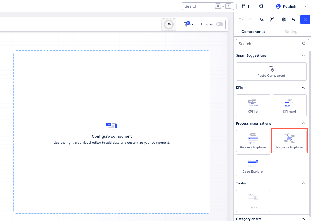
In View Edit Mode, drag and drop the Network Explorer component into your View.
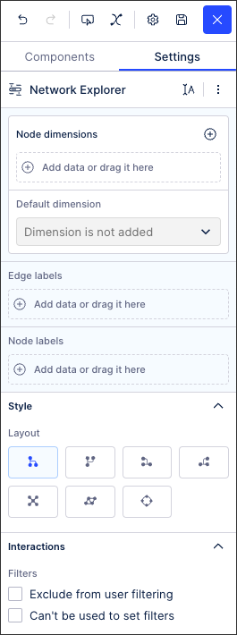
Open the component settings menu and customize your configuration using the following options:
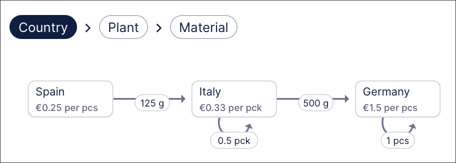
Node dimensions: In the Network Explorer, Objects are synonymous with nodes (a graph term), which are the data points you’d want visualized.
Default dimension: Allows you to define which of the dimensions/ breadcrumbs is selected by default. If none is defined, the first one is taken.
Edge labels: An edge label added to the visual from a Knowledge Model KPI. You can configure more edge labels, but only the first one will be shown.
Edge labels can be used to create a color map which allows you to assign colors to specific values. The assigned colors are then displayed in Network Explorer to indicate where each value is shown.
Node labels: A node label added to the visual from a Knowledge Model KPI. You can configure more node labels, but only the first one will show on the node. The others will display in the context menu.
Node labels can be used to create a color map which allows you to assign colors to specific values. The assigned colors are then displayed in Network Explorer to indicate where each value is shown.
Layout: Select how the Network Explorer is visually displayed in your view from the following layout options:
Hierarchical layouts: top to bottom, bottom to top, left to right, right to left.
Based on spring force algorithms: Use for larger networks, use for smaller networks.
Circular: A circular layout arranges all nodes around a circle, avoiding a strict hierarchy. This is helpful when you want to give equal visual weight to all activities, instead of prioritizing start/end events like in process models.
World map: Chart out the network graph based on its location. To configure the world map layout, see: Configuring the world map layout for Network Explorer
Exclude from user filtering: When a user is filtering the entire view, this component will remain unfiltered.
Can't be used to set filters: While the user can interact with this component, their selections can't then be used to filter the whole view.
Click Interactive Mode and preview your button configuration.
Optional: To see the latest version of your View, deploy the package.
To enable the world map layout, you need to specify the Longitude and Latitude for each node in its data settings. As a best practice, always wrap these coordinates in the AVG function. This ensures the layout handles different node granularities appropriately.
To configure this world map layout, follow these steps:
In the Network Explorer component settings, go to the data settings the main node.
Add data to the Latitude.
In the video example below, the PQL query used is:
AVG ("o_custom_MATERIALS"."Latitude")In the Knowledge sidebar, aggregate the Latitude column with the Average transformation.
Repeat steps 2 and 3 for the longitude.
In the video example below, the PQL query used is:
AVG ("o_custom_MATERIALS"."Longitude")Under the Layout section in the Network Explorer component setting, select the World Map layout.
Creating reusable color rules in the Network Explorer component allows you to create a color map and then assign specific colors to each value. You can assign colors to values for both edges and nodes on the Settings tab for your Network Explorer. Those colors are then shown in the Network Explorer to indicate where each value is used.
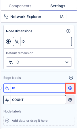
To create a color rule for an edge or node, click the gear icon next to an Edge label or Node label field:
Click the gear icon next to an Edge label or Node label.
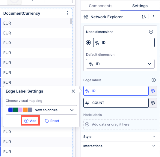
In the Label Settings menu, click the “Add” link.
Choose the type of color mapping you want to use from the Add Visual mapping window and assign values. Node and edge labels containing text values can be color mapped by category, while labels with numeric values can utilize either a gradient or threshold mapping.
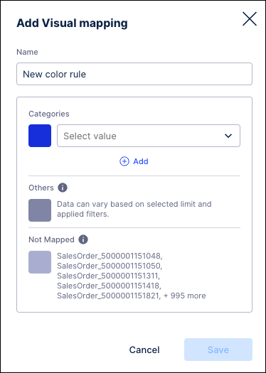
Add Visual mapping window for text values
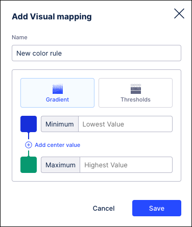
Add Visual mapping window for numeric values
Note
Categorical color mapping is only applicable to edge and node values in a text format.
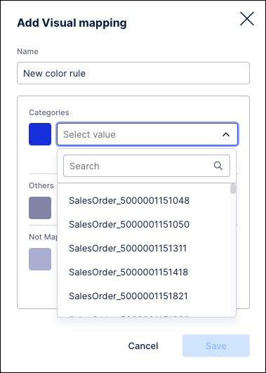
In the Add Visual mapping window, enter a name for this color rule.
In the Categories section, select a value from the dropdown.
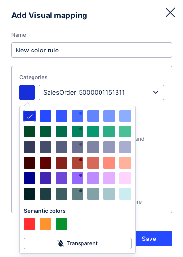
Click the color swatch to assign a different color.
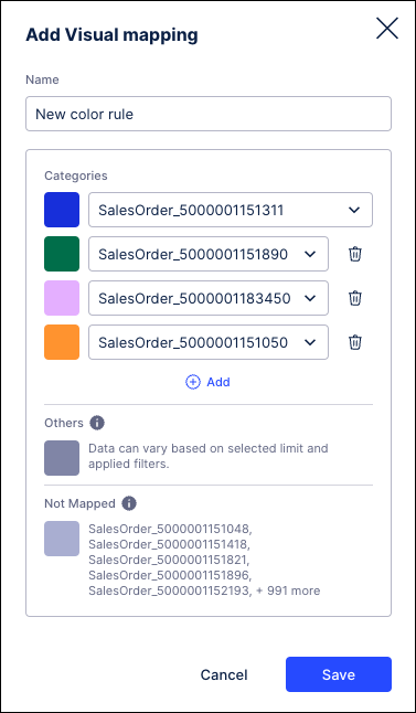
Click the Add link.
Repeat these steps to assign additional values to this color mapping.
Click Save when finished.
By using gradient coloring for your events, you can choose how your values are colored based on their relation to the minimum, center, and maximum values in the range.
Note
Gradient color mapping is only applicable to edge and node values in a numeric format.
In the Add Visual mapping window, enter a name for this color rule and click the “Gradient” option.
Enter the lowest and highest values you want to display. Click the color swatch to assign a different color to either value, or leave these fields blank to include all data.
Note
If filters are applied to your data or you have drilled down on a node, the actual minimum and maximum values may not be shown in your View. In this scenario, the lowest or highest value displayed will not be colored as expected based on the assigned mapping since they are not the actual minimum and maximum values in your data.
Click the color swatch to change the default value and assign a different color to either value.
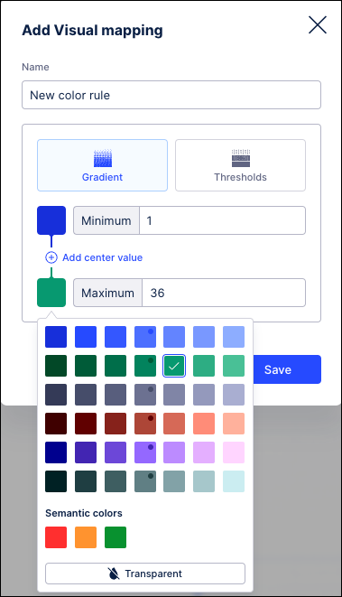
Click the Add center value link and repeat these steps to assign a central value if needed.
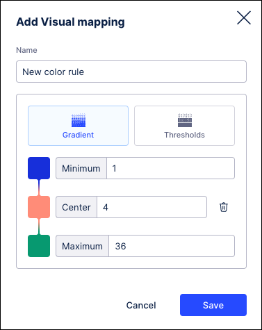
Click Save when finished.
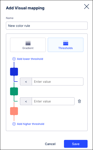
By using threshold column coloring, you can select the values at which your values change colors. Values above and below your defined threshold value will display in the assigned colors. You can further configure this mapping by adding more threshold levels above or below the initial value. Values in your View will change color when they exceed or drop below any of the assigned threshold.
Note
Threshold color mapping is only applicable to edge and node values in a numeric format.
In the Add Visual mapping window, enter a name for this color rule and click the “Thresholds” option.
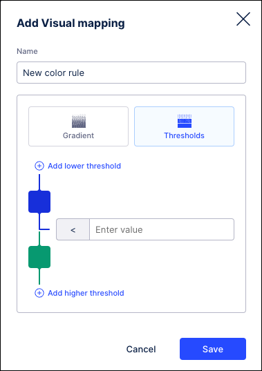
Enter the threshold value in the field provided.
Click the color swatches to choose a different color for values higher and lower than the threshold value.
Click the Add lower threshold or Add higher threshold links to assign additional threshold values and assign colors.
Click Save when finished.
Assign a color map
To assign a color map, click the gear icon.
In the Label Settings menu, choose the color mapping you want to use.
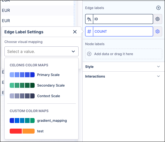
Save your View and the assigned colors are displayed in your Network Explorer to indicate where each value is used.