Creating and managing systems
System objects represent the IT systems, applications, or tools used to support or automate business processes. These objects help define the technical landscape and show which systems are involved in executing or enabling specific tasks within a process.
In the following example, the Process Designer has been used to map out a company's systems:
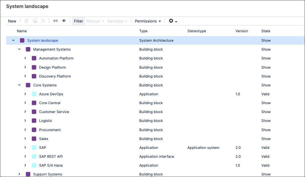
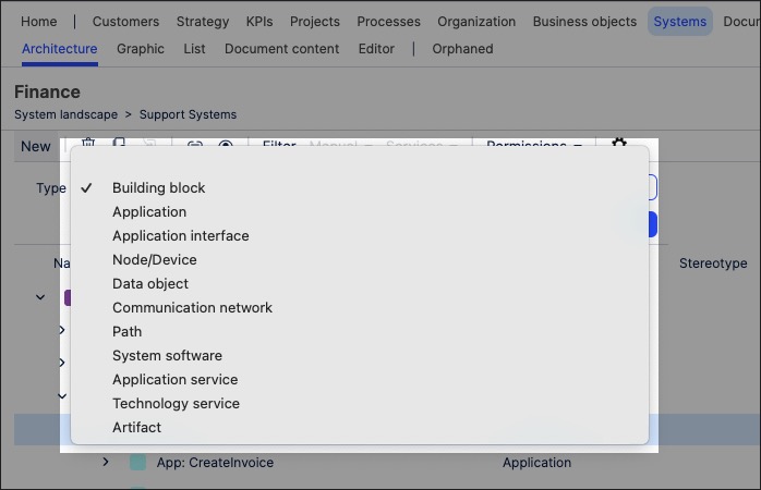
When creating system objects in Process Designer, you can select the following system types by default (though your individual environment may have different options here):
Building block
Application
Application interface
Node / device
Data object
Communication network
Path
System software
Application service
Technology service
Artifact
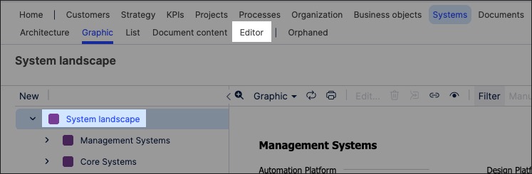
To create standards objects in Process Designer editor mode as an architect:
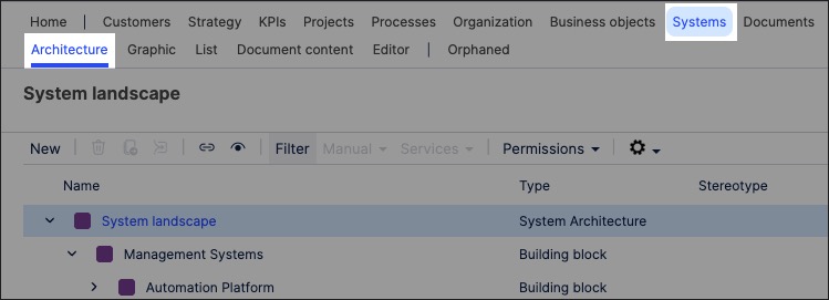
Click Systems - Architecture.
Select the domain to associate the systems object to.
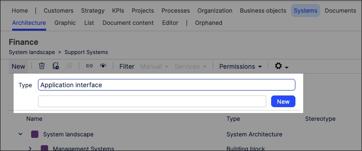
Choose a system type, add a systems object name , and click New.
In this example, we're creating an Application interface:
The systems object is created and set to version 0.1 with the state 'In progress'.
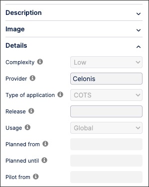
With the systems object side panel open, configure the systems attributes. This includes the system details, including the provider and the access information:
The systems object is now available and can be linked to within a process or task.
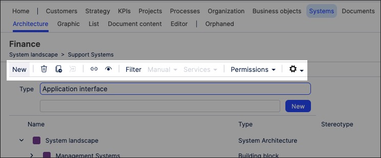
You can manage existing standards objects by returning to the Systems screen and either editing the object details or by using the toolbar:
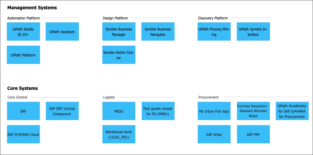
You can also create systems graphics using the content you've previously created. This enables you to visually map out the structure and contents of your organization's system content, such as in the following example
To create a systems graphic in Process Designer editor mode as an architect:
Click Systems - Graphic.
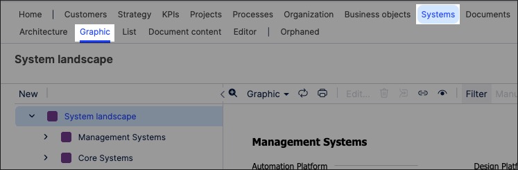
Select the object that you want to create the graphic for and then click Editor.
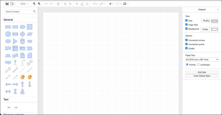
The editor loads and is pre-loaded with the related repository objects from the layer you selected.
Use the drag and drop editor to create the graphic, utilizing the graphic editor features.
Click Save.
Graphic editor features
When creating graphics using the editor, you have the following features available:
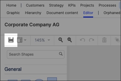
Toolbar: This controls the following features:
Save: Save the current graphic, updating the graphic displayed in the Hierarchy area.
View: Display and hide the format panel, graphic outline, and layers panels.
Zoom / view controls: Controls the view of the editor.
Undo/redo: Effective for the last three changes.
Delete: Removes the existing graphic element.
Front / back layering: Moves the selected element forwards or backwards.
Fill / line / shadow: Configure the colors and shadow for the selected elements.
Connections / waypoints: Add connections between elements and choose the connection style.
Add link / image: Add external elements to the graphic, such as interactive links and uploaded images.
Flow: Automatically organize the selected elements based on how they should flow into each other (such as horizontally or vertically).
