LINK_PATH_SOURCE - LINK_PATH_TARGET
Description
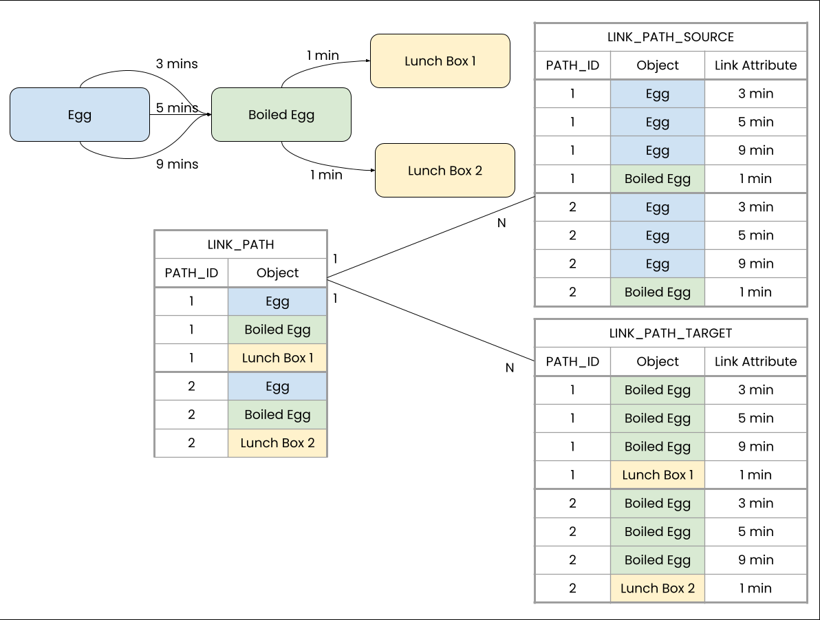
The LINK_PATH_SOURCE - LINK_PATH_TARGET operators return tables containing the links, respectively joined to source or target object, that were used during LINK_PATH traversal.
The output of LINK_PATH_SOURCE/LINK_PATH_TARGET is a column with all links of all paths contained in the LINK_PATH result table. Each row's data corresponds to the value of the traversed link in the specified mapping table column. The generated columns are joined to LINK_PATH's activity table in a N:1 fashion.
Syntax
LINK_PATH_SOURCE ( link_path_table , mapping_table1.column [, mapping_table2.column ] ... )
LINK_PATH_SOURCE ( link_path_table.column , mapping_table1.column [, mapping_table2.column ] ... )
LINK_PATH_TARGET ( link_path_table , mapping_table1.column [, mapping_table2.column ] ... )
LINK_PATH_TARGET ( link_path_table.column , mapping_table1.column [, mapping_table2.column ] ... )
NULL handling
Object Link mapping table entries with NULL values in the IN or OUT column will register the object specified in the none-NULL entry. However, no link will be added to the Object Link graph.
NULL values in the
mapping_table.columnare retained in the output.
Warning
Result table size: As the result contains all links that are used when traversing the graph, with multi-links the size of the table can become really large. The current limitations documented in Engine Limitations also hold for the result of LINK_PATH_SOURCE/LINK_PATH_TARGET. This means that the hard upper limit of rows for the result column of LINK_PATH_SOURCE/LINK_PATH_TARGET is 5 billion rows, and the recommended limit of rows is 800 million rows. In the following example you can see how the amount of rows in the LINK_PATH_SOURCE and LINK_PATH_TARGET table grows with the amount of multi-links.
Examples
[1]
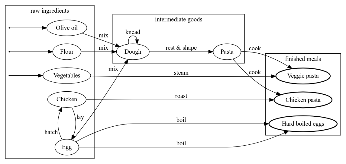
This example lists all links that were traversed from any raw ingredient involved in producing 'Hard boiled eggs'. Note that the result of this example is independent of whether we use | ||||||||||||||||||||||||||||||||||||||||||||||||||||||||||||||||||||||||||||||||||||||||||||||||||||||||||||||||||||||||||||||||||
| ||||||||||||||||||||||||||||||||||||||||||||||||||||||||||||||||||||||||||||||||||||||||||||||||||||||||||||||||||||||||||||||||||
|
[2] This example shows how to solve the issue of having multiple links per pair of objects by utilizing a PU-operator. We can see that the result contains | |||||||||||||||||||||||||||||||||||||||||||||||||||||||||||||||||||||||||||||||||||||||||||||||||||||||||||||||||||||||||||||||||||||||||||||||
| |||||||||||||||||||||||||||||||||||||||||||||||||||||||||||||||||||||||||||||||||||||||||||||||||||||||||||||||||||||||||||||||||||||||||||||||
|
[3] Since individual paths consist of multiple objects and these objects have multiple links associated with them, we need to resolve two consecutive N:1 connections if we want to relate link information to a single path. In this example, we calculate how many paths traverse the same objects, starting from eggs. Before we multiply the numbers of available links between connected objects, we have to explicitly ignore 0 counts by setting them to | |||||||||||||||||||||||||||||||||||||||||||||||||||||||||||||||||||||||||||||||||||||||||||||||||||||||||||||||||||||||||||||||||||||||
| |||||||||||||||||||||||||||||||||||||||||||||||||||||||||||||||||||||||||||||||||||||||||||||||||||||||||||||||||||||||||||||||||||||||
|