Creating and managing organizational objects
Organizations (or organizational units) represent the structural elements of a company or enterprise, such as departments, teams, branches, or entire business units. They help define who is responsible for what, and where tasks, processes, or decisions take place within the organization.
In Process Designer, you can map out your organizational structure using repository objects. These include the following objects:
Organizational units (which can be stereotyped as a company, department, division, staff position, or team)
Positions
Groups
Roles
Locations
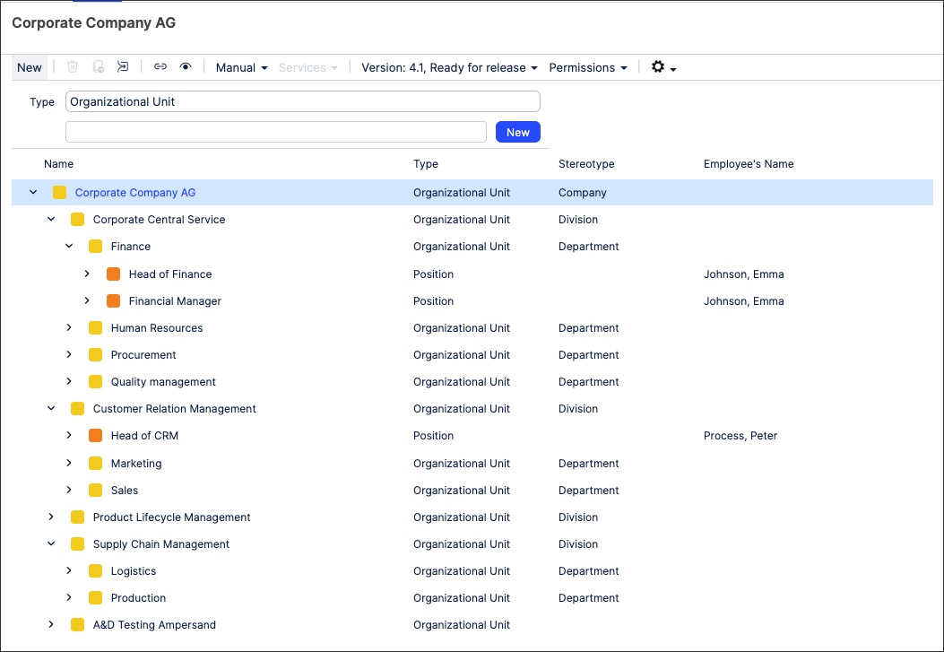
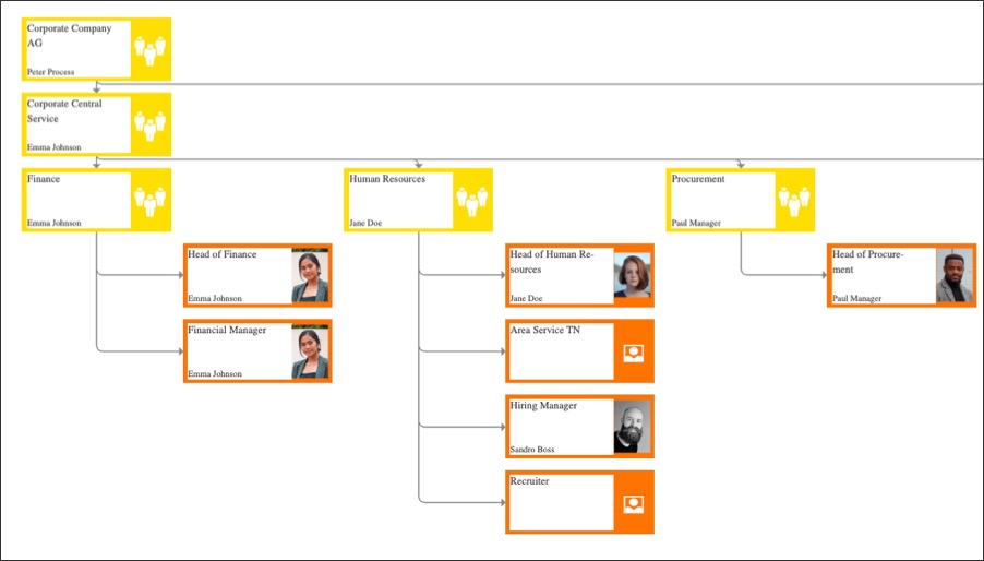
In this example, the Corporate Company AG org. structure has been modeled out of repository objects:
You can also create and view the org. structure as a graphic, often referred to as an 'org chart'. To learn more about creating an org. graphic, see Diagram modes / layouts .
To create organizational objects in Process Designer editor mode as an architect:
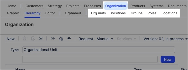
Click Organization and then select the object type you want to create - choosing from Org units, Positions, Groups, Roles, and Locations.
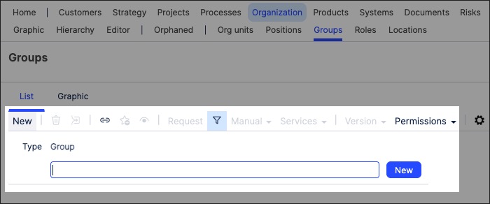
Click New, add an object name, and then click New.
The object is created and added to the Hierarchy overview.
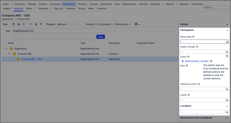
Click the object to open its side panel, enabling you to add further details about the organizational object.
This can included assigning org. objects such as locations and roles to other org. objects. For example, adding locations and roles:
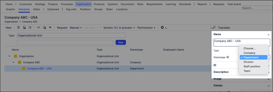
If you've created an Org unit, you can then use the Stereotype field to change the Org unit into the following object types:
Company
Department
Division
Staff position
Role
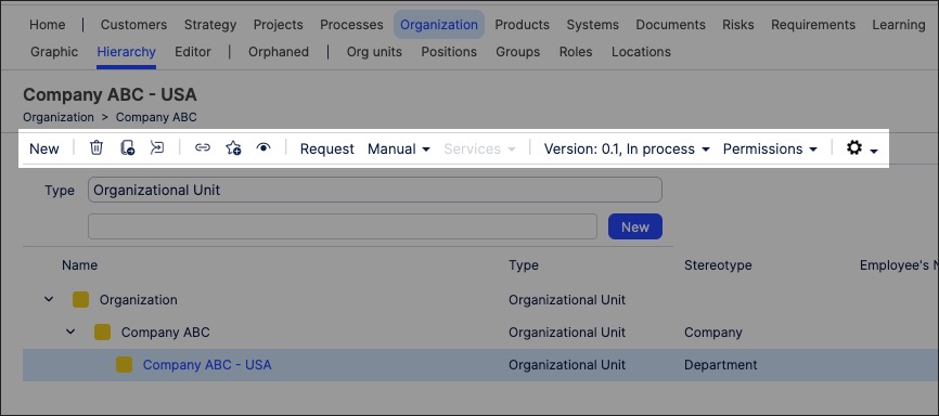
You can manage existing organizational objects by returning to the Organization screen and either editing the details or by using the toolbar:
You can also create organizational charts using the repository objects you've previously created. This gives you a visual diagram of how the organization is structured, often referred to as an 'Org chart' by many companies.
For example, this is a cropped version of the Corporate Company AG graphic:
To create an organizational graphic in Process Designer editor mode as an architect:
Click Organization - Graphic. This loads the full org. structure.

Select the organizational object that you want to create the graphic for and then click Editor.
In this example, we're editing the Corporate Company AG org chart.
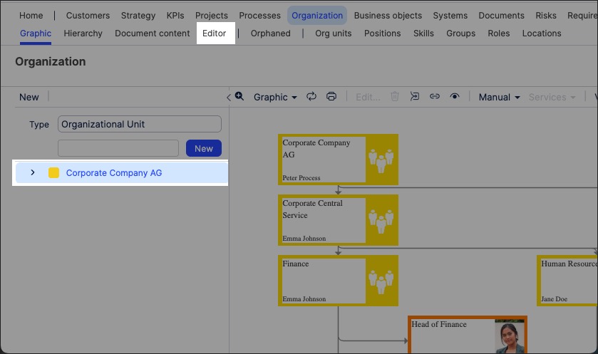
The editor loads and is pre-loaded with the related repository objects from the layer you selected.
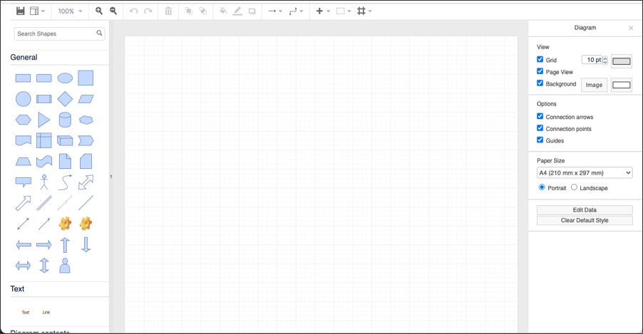
Use the drag and drop editor to create the graphic, utilizing the graphic editor features.
Click Save.
Graphic editor features
When creating graphics using the editor, you have the following features available:
Toolbar: This controls the following features:
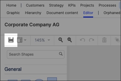
Save: Save the current graphic, updating the graphic displayed in the Hierarchy area.
View: Display and hide the format panel, graphic outline, and layers panels.
Zoom / view controls: Controls the view of the editor.
Undo/redo: Effective for the last three changes.
Delete: Removes the existing graphic element.
Front / back layering: Moves the selected element forwards or backwards.
Fill / line / shadow: Configure the colors and shadow for the selected elements.
Connections / waypoints: Add connections between elements and choose the connection style.
Add link / image: Add external elements to the graphic, such as interactive links and uploaded images.
Flow: Automatically organize the selected elements based on how they should flow into each other (such as horizontally or vertically).
