Define a Subprocess
Model a subprocess
By default, Celonis Process Management offers modeling according to the BMPN 2.0 methodology.
Celonis Process Management provides automated, efficient process sequences. The program offers the selection of only those process flow objects that allow process modeling using the correct methodological approach.
Note
Before modeling, please ensure that no Scope filters are set – to avoid discrepancies or redundancies.
Modeling processes in the graphical view
To access process modeling, click the Process House tile in Graphical Views on Process Designer HOME or select the graphic sub-navigation in PROCESSES.
The author is authorized to create a new subprocess on the left side of the Navigation Content. The author selects a process in the navigation tree under which the new Subprocess will be created, enters the name, and clicks New. Now, a process can be modeled.
Click New on the Main Content toolbar to create the first process flow object Start. This step is mandatory for each subprocess, and you can use multiple Start objects.
Proceed to create additional process flow objects. Click Start to display a process toolbar for selecting subsequent process flow objects: task, subprocess, interface shape, gateways, and events. Use the mouse-over function to view details about each item.
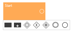
Task | Process step/individual activity within a chronologically logical process sequence |
Subprocess | Serves to embed a further, self-contained sub-process, which is automatically placed one level below in the navigation tree |
Loop | A subprocess that repeats a task. |
Sequential multi-instance | A subprocess that sequentially executes a task for all items. |
Parallel multi instance | Subprocesses that execute in parallel. |
Interface shape | Refers to another existing Process house subprocess and serves as a placeholder if the reference does not exist. To learn how to create a process reference, please refer to Edit a Sub Process. |
Or gateway | Allows one or more paths (for each condition). |
Either-or gateway | Splits the process into two or more mutually exclusive alternatives. |
And gateway | All subsequent paths are executed in parallel. |
Event | Marks the achievement of a defined condition within the process, such as a milestone. |
End | It ends the process sequence and is mandatory; it can be used multiple times. |
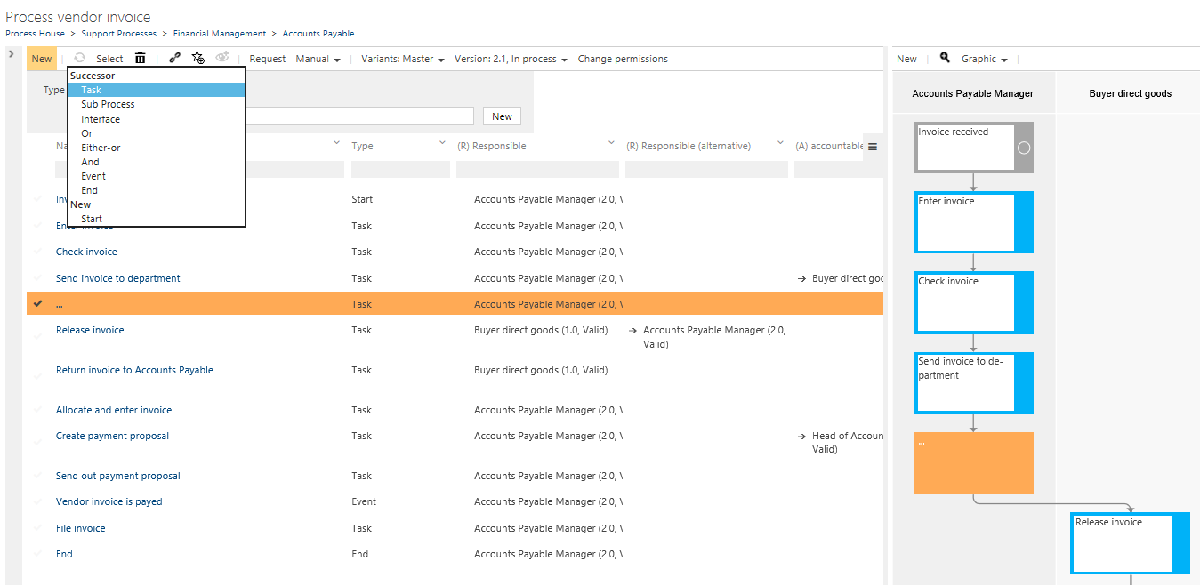
Suppose multiple process flow objects have been created and you click an object. In that case, the Process toolbar is displayed at the top and the bottom to offer various modeling options for predecessors and successors.
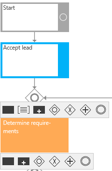
Process Designer automatically arranges the process flow objects and their connection objects.
The process flow object End is required at the end of a sub-process. Multiple End objects can be used.
Modeling in the table view
Process flows can also be modeled quickly and efficiently in a Sub-Navigation table. This is particularly recommended for structurally simple process flows with few branches.
Tasks, events, or gateways are also created in the toolbar via New. Objects to be linked, such as roles, can be selected in the same line.
If process flow objects are to be added within an existing process, the line under which the new object is to be created must first be selected.
The graphical implementation of the process flow is displayed in the window to the right.